- Whatsapp: +86 15967777035
- Email: [email protected]

From component roles and correct sizing to NEC/IEC rules and a build-it-yourself selector — a practical guide for panel builders, EPCs, and plant engineers specifying motor protection.
Korlen — Professional Circuit Breaker & Motor Control Manufacturer Since 1985
38,000 m² facility | 1,000+ employees | 50+ patents | Certified: ISO, CB, CE, SEMKO, SIRIM, NF, TSE, SNI, PCT, RoHS | Trusted by top-500 global enterprises
Searching “Manual Motor Starter (MMS) vs Thermal Overload Relay” suggests two interchangeable devices. They are not. The confusion is one of layers: an MMS is a finished, sealed motor-protection product, while a thermal overload relay is a single protective component that only does its job when assembled with other devices.
Specify the wrong mental model and you end up with one of two failures:
Buying only a thermal overload relay and calling it “motor protection” leaves the motor with no short-circuit protection and no controlled start/stop — a code violation and a fire risk.
Assuming every motor needs a sealed MMS when a contactor + overload relay + breaker already in your panel does the same job — at lower cost and easier service.
The two devices become clear once you see what each one actually contains. Let’s start with the all-in-one unit.
A Manual Motor Starter (MMS) is a compact, three-in-one electromechanical device that combines in a single enclosure:
What an MMS contains
Because it bundles all three functions, an MMS is popular for simple, local-controlled machines — pumps, conveyors, fans, compressors, and small process skids — where a single catalog number simplifies procurement and wiring. Magnetic-only MMS variants exist when short-circuit protection alone is needed.
Note: Korlen’s motor-control portfolio centers on the individual components (contactors, thermal overload relays, and circuit breakers) rather than a sealed MMS. The rest of this guide shows how to assemble equivalent — and often more flexible — protection from those components.
A thermal overload relay (OLR) is a protective relay — not a switch and not a breaker. Its only job is to open a control circuit when motor current stays above a safe threshold for too long, protecting the winding from thermal damage during sustained overload.
What a thermal overload relay does — and does NOT do
That is why an overload relay always rides behind a contactor (for control) and a short-circuit protective device such as an MCCB or MCB. As the c3controls basics guide puts it, a motor starter is fundamentally a contactor + overload relay assembly — the relay alone is just one half of the pair.
Read this as “finished product vs. one component,” not as a like-for-like shootout:
| Attribute | Manual Motor Starter (MMS) | Thermal Overload Relay (OLR) |
|---|---|---|
| Device class | Finished motor-protection product | Single protective component |
| Manual ON/OFF control | Yes (built-in switch) | No |
| Short-circuit protection | Yes (magnetic trip) | No |
| Overload protection | Yes (thermal) | Yes (its only function) |
| Isolation / disconnect | Yes | No |
| Works alone? | Yes — self-contained | No — needs contactor + SCPD |
| Remote / automated control | Manual only (unless paired with contactor) | Supports remote via contactor coil |
| Serviceability | Replace as a unit | Relay replaceable independently |
| Typical standard | IEC/UL 60947-4-1 | IEC/UL 60947-4-1 |
Whether you buy a sealed MMS or build from components, a code-compliant motor branch circuit needs four functions. NEC Article 430 (and its IEC equivalents) require all four:
Four required layers (in power-flow order)
An MMS crams all four into one box. A contactor + thermal overload relay delivers layers 3 and 4, and you add layers 1–2 with a disconnect and an MCCB (or MCB for small motors). The protection outcome is identical — the difference is packaging, cost, and serviceability.
Choose an MMS when…
Choose contactor + OLR when…
Bottom line: the MMS wins on simplicity; the component starter wins on flexibility and scale. Both satisfy the same protective intent.
Correct sizing is where most motor-protection mistakes happen (see Common Mistakes below). Follow the nameplate and the code:
Example: a 60 A motor with a relay that does not build in the 125% factor → set the relay to 75 A (60 × 1.25). If the relay builds it in, set to 60 A. Setting it to 50 A would nuisance-trip under load; setting it to 156% (double-counting) would leave the motor under-protected.
Match your motor duty to the required layers. (Pure HTML table — no JavaScript, safe for Classic Editor.)
| Motor duty | Disconnect | Short-circuit (SCPD) | Control | Overload | MMS viable? |
|---|---|---|---|---|---|
| Small pump/fan ≤ 4 kW, local | MMS / switch | In MMS or MCB | MMS | In MMS | Yes |
| Conveyor, remote/PLC start | Disconnect SW | MCB / MCCB | Contactor | Thermal OLR | No (needs contactor) |
| Compressor / hard start | Disconnect SW | MCCB | Contactor | OLR Class 20/30 | Sometimes |
| Motor in MCC / large ≥ 55 kW | MCC disconnect | MCCB | Contactor | OLR / electronic | No |
| VFD-driven motor | Disconnect SW | MCCB (upstream) | VFD | VFD internal (OLR spare) | No |
1. Using an overload relay as the only “motor protection.” A thermal relay gives no short-circuit protection and no isolation. NEC 430 requires separate SCPD and a disconnect — a starter without an overload relay is also non-compliant.
2. Setting the overload too low. A 60 A motor on a relay left at 50 A trips under normal load. Set to nameplate FLA (or FLA × 1.25 if the factor isn’t built in).
3. Double-counting the 125% factor. Adding 25% to a relay that already includes it pushes protection to ~156% — the motor is left under-protected. Read the relay instructions.
4. Wrong trip class for the load. A Class 10 relay on a hard-start compressor nuisance-trips; a Class 20/30 relay tolerates the longer inrush.
5. Ignoring magnetic (short-circuit) setting. If adjustable, set it above the locked-rotor/inrush current (can reach 600–800% of FLA) so it doesn’t trip on start yet still clears a fault.
Korlen manufactures the full set of motor-protection building blocks under one certified quality system — so you can assemble a coordinated starter instead of buying a sealed MMS, with the same international certifications (ISO 9001, CB, CE, SEMKO, SIRIM, NF, TSE, SNI, PCT, RoHS).
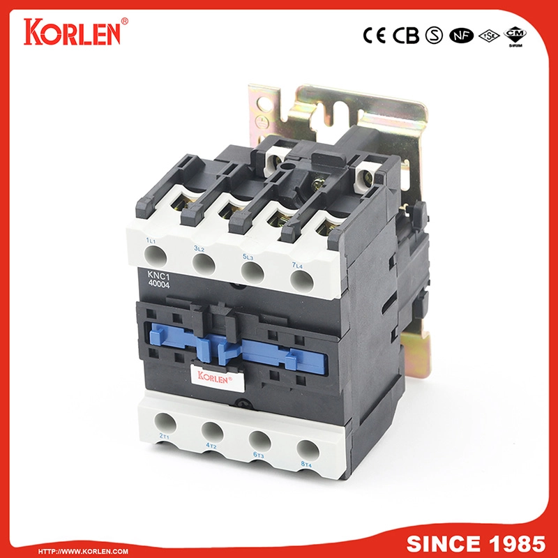
AC Contactor
The control layer — starts/stops the motor locally or via PLC/VFD, with a coil matched to your control voltage.
Thermal Overload Relay
The overload layer — adjustable bimetallic protection with phase-loss sensing, sized to your motor FLA.
MCCB / MCB (Short-Circuit)
The SCPD layer — clears faults in milliseconds; choose MCB for small motors, MCCB for larger or coordinated boards.
Note: Exact Korlen contactor / thermal overload relay model series (e.g., KNC / KTR prefixes) should be inserted from the product catalog before publishing — the live product pages currently show generic descriptions.
1. What is the difference between a Manual Motor Starter (MMS) and a thermal overload relay?
An MMS is a finished, sealed unit that combines a disconnect switch, magnetic short-circuit protection, and thermal overload protection. A thermal overload relay is only the overload element and must be paired with a contactor and a short-circuit device to start and protect a motor. Build your own assembly from Korlen AC contactors & thermal overload relays.
2. Can a thermal overload relay alone start and protect a motor?
No. A thermal overload relay only opens the control circuit on sustained overcurrent — it cannot switch motor power, clear a short circuit, or provide isolation. You need a contactor for control and an MCCB/fuse for short-circuit protection. See the Korlen MCCB range for the short-circuit layer.
3. Do I need both a contactor and an overload relay?
Yes, for any remotely controlled or automated motor. The contactor provides start/stop control; the overload relay provides thermal protection. Together they form a motor starter — the foundation of the NEC 430 requirements. Explore Korlen’s industrial electrical components.
4. What is the difference between an MMS and a contactor + overload relay starter?
Functionally they deliver the same four protective layers. An MMS packs them in one sealed box (simple, local control); a contactor + overload relay + breaker spreads them across serviceable parts (flexible, remote-capable, scalable to MCCs). Compare both in the Korlen AC contactor lineup.
5. Is a motor starter without overload relay protection allowed by code?
No. NEC Article 430 requires motor overload protection on every motor branch circuit; a starter with only a contactor and a breaker is non-compliant and leaves the winding exposed to thermal damage. Add a Korlen thermal overload relay to close the gap.
6. How do I size a thermal overload relay for my motor?
Set it to the motor’s nameplate FLA, never exceeding 125% of FLA per NEC 430. If the relay already includes the 125% factor, set it to the nameplate current; otherwise add 25%. Match the trip class to the starting profile. Get the right Korlen thermal overload relay for your FLA range.
7. What is trip class 10, 20, 30 and which should I choose?
Trip class is the time the relay takes to trip at 10× FLA: Class 10 (2–10 s) for normal starts, Class 20/30 for high-inertia or hard-start loads like compressors and crushers. Choosing too fast causes nuisance trips; too slow risks winding damage. Korlen’s AC contactors & thermal overload relays cover standard and heavy-start duties.
8. When should I use an MMS vs building a starter from components?
Use an MMS for small, locally controlled motors where one catalog number and a compact footprint win. Build from a contactor + overload relay + breaker for remote control, large motors, MCC integration, or field-serviceable spares. Start with the Korlen low-voltage circuit breakers catalog.
9. What standards apply to motor starters and overload relays?
Both are covered by IEC/UL 60947-4-1 (motor controllers and starters); short-circuit devices by IEC 60947-2 / UL 489; assemblies by IEC 61439. Korlen components carry ISO 9001, CB, CE, SEMKO, SIRIM, NF, TSE, SNI, and more — see the Korlen industrial components page.
10. How do I build a complete motor starter with Korlen components?
Assemble: (1) disconnect switch, (2) MCB/MCCB for short-circuit, (3) Korlen AC contactor for control, (4) Korlen thermal overload relay for overload — sized to FLA at the correct trip class. For a coordinated bill of materials, review the Korlen MCCB and contactor lines, or contact the Korlen engineering team.
A Manual Motor Starter (MMS) and a thermal overload relay are not competitors — they sit at different levels of the same protective chain. An MMS bundles disconnect, short-circuit, and overload protection into one sealed, locally-controlled box; a thermal overload relay is a single, essential component that only works when assembled with a contactor and a short-circuit device. Choose the MMS for simplicity on small local motors; choose a contactor + overload relay + breaker for flexibility, remote control, and scalable motor control centers. Size the overload relay to the motor FLA, pick the right trip class, and you get code-compliant protection either way.
Recommended further reading (internal blog links to add after publishing): AC MCB vs DC MCB: A Complete Selection Guide · MCB Trip Curves: Matching Type B, C, D to Inductive Motor Loads · MPCB vs MCCB: Motor Protection for Inductive Loads · Sourcing Low-Voltage Switchgear from China: The Ultimate Verification Guide · ACB vs MCCB: Main Breaker Selection for Heavy Industrial Switchgear.
Build Your Optimal Motor Protection with Korlen
Whether you prefer the simplicity of a sealed MMS or the flexibility of a contactor + overload relay + breaker starter, Korlen delivers the certified building blocks from one quality system.
Need a tailored motor-starter bill of materials? Contact the Korlen engineering team.
© 2026 Korlen (GAONENGGELE ELECTRICAL SHARES CO., LTD.). This guide is for general engineering reference; always verify selections against the latest IEC/UL standards and a qualified design review.
GAONENGGELE ELECTRICAL SHARES CO.,LTD.
Privacy Policy | SiteMap
Copyright GAONENGGELE ELECTRICAL SHARES CO.,LTD.