- Whatsapp: +86 15967777035
- Email: [email protected]

Product Features
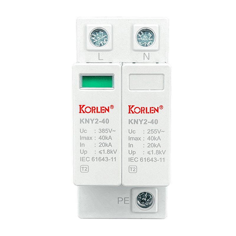
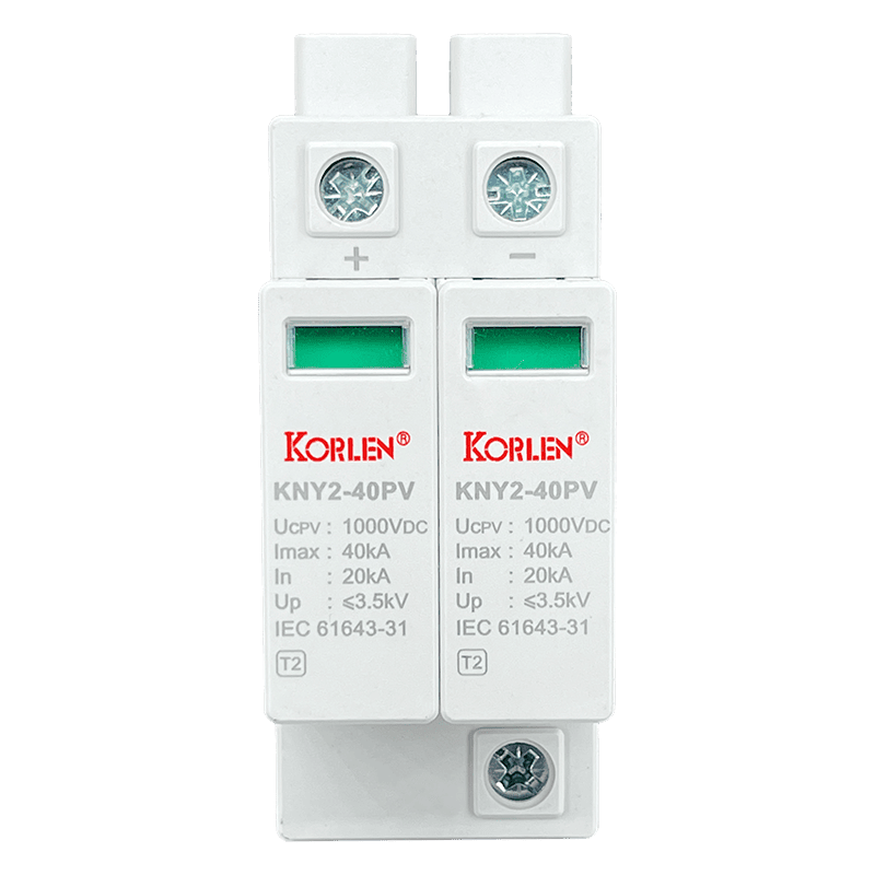
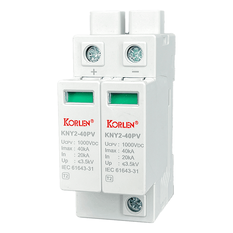
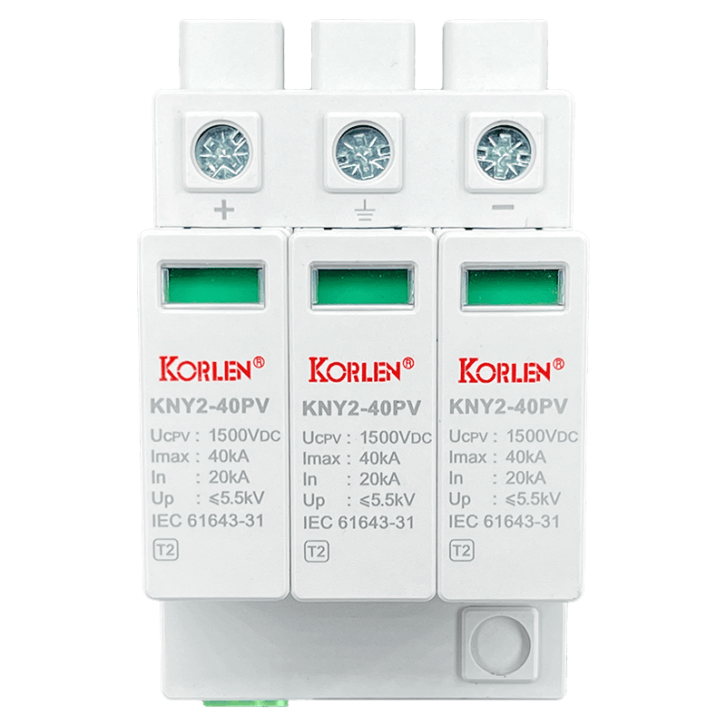
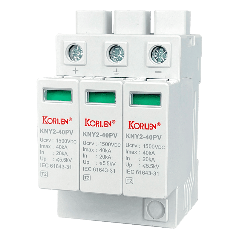
U-shaped structure, voltage-limiting type combination, with both differential mode and common mode protection modes.
Built-in overheating and overcurrent protection mechanisms.
Local fault indication: the indicator shows white during normal operation, and turns red after tripping and failure.
Optional alarm module to realize remote telemetry function.
Integrated structural design with large discharge capacity.
Technical data
| Type 2 Ⅱ | |||||
| Model/Specification | KNY2-PV600 | KNY2-PV800 | KNY2-PV1000 | KNY2-PV1200 | KNY2-PV1500 |
| Maximum Continuous Operating Voltage Uc (VDC) | 600 | 800 | 1000 | 1200 | 1500 |
| Nominal Discharge Current In 8/20µs (kA) | 20 | 20 | 20 | 20 | 20 |
| Maximum Discharge Current Imax 8/20µs (kA) | 40 | 40 | 40 | 40 | 40 |
| Voltage Protection Level Up (kV) | ≤2.5kV | ≤3.2kV | ≤3.5kV | ≤4.0kV | ≤5.5kV |
| Response Time (ns) | <25 | ||||
| Protection Class: | IP20 | ||||
| Fault Status Indicator | Green = Normal, Red = Fault | ||||
| Remote Signaling Function | Optional | ||||
| Number of Poles | 2P | 2P, 3P | 2P, 3P | 2P, 3P | 2P, 3P |
| Connection Configuration | 2P-U | 2P-U, 3P-Y | 2P-U, 3P-Y | 2P-U, 3P-Y | 2P-U, 3P-Y |
| Operating Temperature Range (°C) | -40~+70 | ||||
| Relative Humidity | ≤95%(25°C) | ||||
| Input Conductor Cross-section Area (mm²) | 6~25 (Multi-strand copper wire), recommend>10mm² | ||||
| Installation Method | 35mm DIN RAIL | ||||
| Type 1+Type 2 Ⅰ+Ⅱ | |||||
| Model/Specification | KNY2-PV600/B+C | KNY2-PV800/B+C | KNY2-PV1000/B+C | KNY2-PV1200/B+C | KNY2-PV1500/B+C |
| Maximum Continuous Operating Voltage Uc (VDC) | 600 | 800 | 1000 | 1200 | 1500 |
| Nominal Discharge Current In 8/20µs (kA) | 20 | 20 | 20 | 20 | 20 |
| Maximum Impulse Current Iimp 10/350µs (kA) | 6.5 | 6.5 | 6.5 | 6.5 | 6.5 |
| Maximum Discharge Current Imax 8/20µs (kA) | 40 | 40 | 40 | 40 | 40 |
| Voltage Protection Level Up 8/20µs (kV) | ≤2.5kV | ≤3.2kV | ≤3.5kV | ≤4.0kV | ≤5.5kV |
| Response Time (ns) | <25 | ||||
| Protection Level: | IP20 | ||||
| Fault Status Indicator | Green = Normal, Red = Fault | ||||
| Remote Signal Function | Optional | ||||
| Number of Poles | 2P 3P | 3P | 3P | 3P | 3P |
| Connection Configuration | 2P-U 3P-Y | 3P-Y | 3P-Y | 3P-Y | 3P-Y |
| Operating Temperature Range (°C) | -40~+70 | ||||
| Relative Humidity | ≤95%(25°C) | ||||
| Input Conductor Cross-section Area (mm²) | 6~25 (Multi-strand copper wire), recommend>10mm² | ||||
| Installation Method | 35mm DIN RAIL | ||||
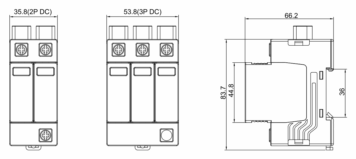
Dimensions(mm)
GAONENGGELE ELECTRICAL SHARES CO.,LTD.
Privacy Policy | SiteMap
Copyright GAONENGGELE ELECTRICAL SHARES CO.,LTD.